Embedded Motion Control 2015 Group 3/Drive: Difference between revisions
| (3 intermediate revisions by one other user not shown) | |||
| Line 1: | Line 1: | ||
This page is part of the [ | This page is part of the [[Embedded_Motion_Control_2015_Group_3 EMC03|CST-wiki]]. | ||
= Potential field = | = Potential field = | ||
The type of driving used in the Maze Challenge was Potential Field driving. Although Drive was initially designed to be a separate block in the software design, the potential field driving relies mainly on manipulating LRF data, and the resultant vector could almost immediately be entered into the Pico IO layer. This negated the need for a separate Driving class. The Potential Field method can be seen on | The type of driving used in the Maze Challenge was Potential Field driving. Although Drive was initially designed to be a separate block in the software design, the potential field driving relies mainly on manipulating LRF data, and the resultant vector could almost immediately be entered into the Pico IO layer. This negated the need for a separate Driving class. The Potential Field method can as such be seen on the [[Embedded_Motion_Control_2015_Group_3/Scan|Scan]] page. The rest of this page will be dedicated to the initial methods considered for driving through the maze. | ||
= Collision avoidance = | = Collision avoidance = | ||
| Line 42: | Line 42: | ||
=== ''' Path planning for turning '''=== | === ''' Path planning for turning '''=== | ||
The path planning is the second method that we worked on. Path planning can be used when PICO approaches an intersection. Assume that PICO has to go left on a T-juntion; then only collision avoidance will not be sufficient anymore. So, for instance 0.2 meter before the corner the ideal path to drive around the corner is calculated. This means that Vx, Vy, Va and the time (for turning) have to be determined on that particular moment. | |||
Then basically, | Then basically, | ||
Latest revision as of 10:09, 24 June 2015
This page is part of the CST-wiki.
Potential field
The type of driving used in the Maze Challenge was Potential Field driving. Although Drive was initially designed to be a separate block in the software design, the potential field driving relies mainly on manipulating LRF data, and the resultant vector could almost immediately be entered into the Pico IO layer. This negated the need for a separate Driving class. The Potential Field method can as such be seen on the Scan page. The rest of this page will be dedicated to the initial methods considered for driving through the maze.
Collision avoidance
This is a function that is used to drive through corridors without touching the walls. The function measures the nearest wall and identifies whether it is on its left or right side. There is set a margin in order to avoid a collision. This margin determines when PICO has to adjust its direction. When for instance, a wall on the left is closer than the margin, PICO has to move to the right.
Old drive methods
For the corridor challenge, we tried a driving method based on extracting some key points, but that turned out not to be robust. After the corridor challenge, we then considered three options, of which potential field driving came out as a winner. The two other options use the key point method for driving through straight corridors but use a different approach to taking corners. We called the first one the 'simple method'. Basically, this method is developed as a back-up plan. The second approach uses path planning to drive around corners.
Drive using key points
The initial driving method we considered was based on selecting key points for various situations, and updating the driving inputs according to those. It turned out that robustly determining the key points was virtually impossible in corners, and the following algorithms would fail whenever the key points were lost.
It should be noted that the Drive class is not responsible for deciding whether it is driving in a corridor, so the algorithms are not robust for varying situations - it expects another class to determine exactly what algorithm should be used at any given time.
Straight through corridors

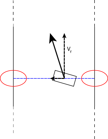
The key points for driving through corridors are the points closest to the robot on the left and right side. Since these points will also be perpendicular to a straight wall, they give all sufficient information (distance from wall as well as direction of wall) for driving through a straight corridor.
First, the angle of the left and right wall is bisected, which gives a direction straight through the corridor. The deviation between the direction of the robot and aforementioned direction results in an angular velocity for the robot through a simple gain.
Next, a set forward velocity vector is created, in the direction straight through the corridor, (Vf in the picture). Furthermore, the distance from the center line results in a sideways velocity vector. These vectors combined give the desired driving vector (bold black arrow in the picture), which is then transformed to the Vx and Vy relative to the robot since the robot may be rotated.
This type of driving was successfully used during the corridor challenge, and resulted in smooth and fast driving.
Driving through corners

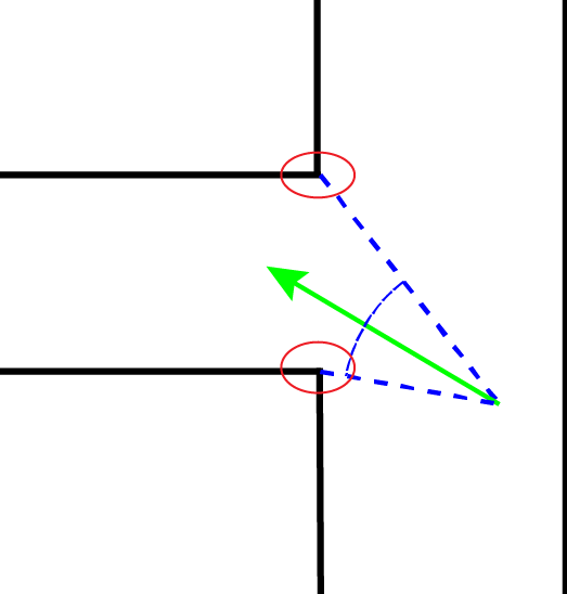
The key points for driving through corners are the two corner points of the corridor Pico is trying to enter. This turned out to be the biggest letdown of this method; extracting the local minimums required while turning was almost impossible to do robustly. Mostly because of this, other options were explored.
On the figure on the right, one option for driving through corners is explored. The robot maintains a constant forward velocity, and makes the corner by varying the angular velocity. First, the desired direction is determined. This is the bisection of the direction to the two corner points, since this vector always points to the exact center of the corridor. Then, an angular velocity is calculated based on the difference between the desired direction and the current robot direction ('error'). A simple gain controller was used, and varying the gain influenced how 'tight' the corner would be made.
Simple method
This approach is the most simple one; this also means that is not the most fancy one. However, it is still important to have this working because we can always use this method when the other methods fail, or use it as a minimal working example in other parts of the software. In addition, we have learned a lot from it and used is as base for the other methods.
In short, the simple method contains 3 steps:
- Drive to corridor without collision.
- Detect opening (left of right) and stop in front of it.
- Turn 90 degrees and start driving again.
This method is a robust way to pass the corridor challenge. Although, it would not be the fastest way.
Path planning for turning
The path planning is the second method that we worked on. Path planning can be used when PICO approaches an intersection. Assume that PICO has to go left on a T-juntion; then only collision avoidance will not be sufficient anymore. So, for instance 0.2 meter before the corner the ideal path to drive around the corner is calculated. This means that Vx, Vy, Va and the time (for turning) have to be determined on that particular moment.
Then basically,
- Driving straight stops;
- Turning with the determined Vx, Vy and Va for the associated time to drive around the corner;
- Driving straight again.
In practice, this method turned out to be very hard. Because it is difficult to determine the right values for the variables.